Analog I/O Modules:
Analog modules are working with PLC which is called from Input and output signal for machine operation. Mostly, using analog Input and digital Input which is delivery to output signal. Analog Reference value standard S7-200-Siemens
- 0-10VDC Signal
- 0-20mA Input signal
- 4-20mA Input signal value
Digital Modules:
Digital modules, on the other hand, deal with discrete digital signals that have two states: ON and OFF. They handle binary input and output signals, typically representing the status or presence of devices or sensors. Digital input modules receive signals from devices like switches, push buttons, or limit switches, detecting their ON/OFF status and transmitting this information to the PLC.
Input Channels:
Analog modules have input channels to receive continuous analog signals, while digital modules have input channels for binary digital signals.
Output Channels:
Analog modules have output channels to generate analog control signals, while digital modules have output channels for binary digital control signals. Digital output modules generate digital control signals to activate or deactivate devices like solenoid valves, relays, or indicator lights based on the PLC’s instructions.
Resolution:
Analog modules have a specific resolution that determines the level of accuracy in converting analog signals to digital data. Higher resolution allows for more precise measurements. Digital modules typically do not have a resolution since they handle binary signals.
I/O Range:
Analog modules have a configurable input/output range to match the signal levels of the connected sensors or actuators. Digital modules typically operate with fixed voltage levels for ON and OFF states.
Communication Interface:
Both analog and digital modules communicate with the PLC’s central processing unit through a communication interface. This allows the PLC to exchange data with the modules for input acquisition and output control.
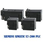
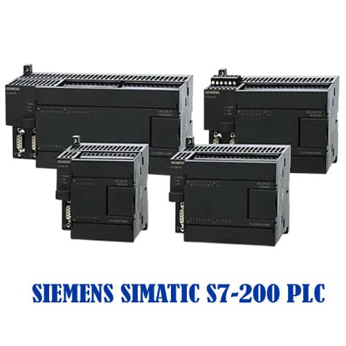
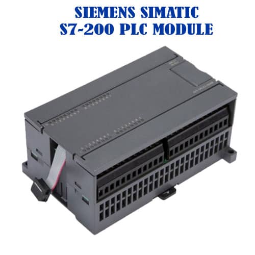
The Siemens SIMATIC S7-200 is a highly successful, yet discontinued Micro PLC series. The relevant discussions and blogs focus primarily on programming tutorials, key features of the successor model S7-200 SMART, and crucial migration guidance to the modern S7-1200 platform.
Programming and Technical Overviews
- Programming Environment: The S7-200 is programmed using STEP 7-Micro/WIN software, which is a key topic in many tutorials.
- Core Concepts: Tutorials frequently delve into the use of basic Ladder Logic instructions, including Bit Level instructions, Timers, Counters, and Comparators.
- CPU Features: Articles often detail the different CPU models (e.g., CPU-221, CPU-224, CPU-226), comparing their built-in I/O, program memory size, and features like High-Speed Counters (HSC) and $\text{RS485}$ communication ports.
- Integration: Some resources discuss connecting S7 PLCs (including the S7-200 and its successors) to modern Industrial Internet of Things (IIoT) platforms like Node-RED for remote monitoring and data sharing.